

We want to keep you in the loop! Our website is currently undergoing some exciting enhancements to provide you with an even better online experience.
Induction heating has been used for various purposes from production technology such as quenching and shrink fitting through to the design of home appliances as in Induction cooking system. Induction heating is the technology based on the eddy current, and it becomes a key issue for design to control the eddy current accurately. However, since the eddy current depends on factors such as geometry, material characteristics, frequency, and temperature, its behavior is complicated.
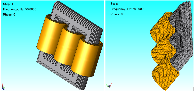
As a precision component, a gear requires an accurate evaluation of dimensional tolerance due to thermal deformation resulting from induction hardening. The main objective of work is a coupled magnetic and thermal analysis of a gear to study elevated temperature process (Fig. 1).
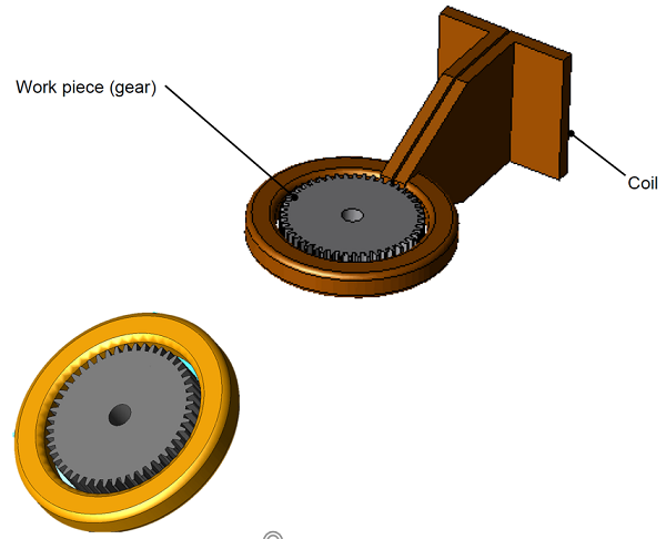
Fig. 1 Gear and induction coil configuration (top) simplified model of the coil for analysis in JMAG (bottom)
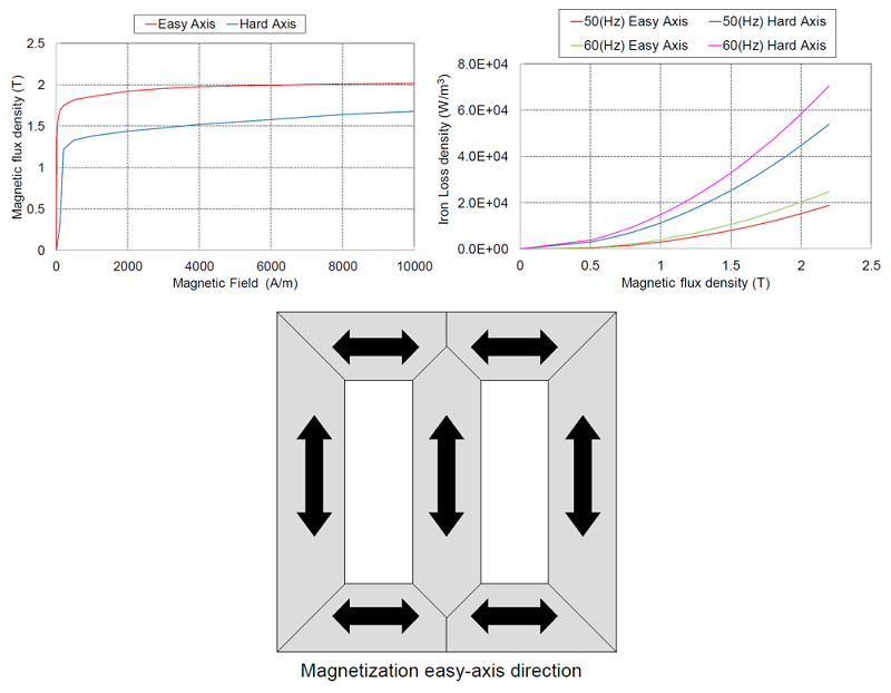
Accurate modeling of induction heating requires precise material data versus temperature for magnetic and thermal analysis. Magnetic susceptibility, electrical conductivity, thermal conductivity, specific heat capacity versus temperature for gear iron material are used in the simulations. Magnetic frequency analysis is used for eddy current losses calculations in the gear at source frequency 10 kHz and transient thermal analysis is used for gear temperature calculations. Two way coupled analysis is performed for magneto thermal analysis. Skin mesh elements of JMAG is used in the gear for accurate modeling of eddy currents (Fig. 2).
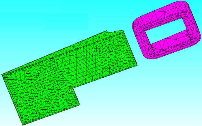
Fig. 2 3D mesh for gear and induction coil (partial model) using skin mesh element for accurate calculation of eddy currents
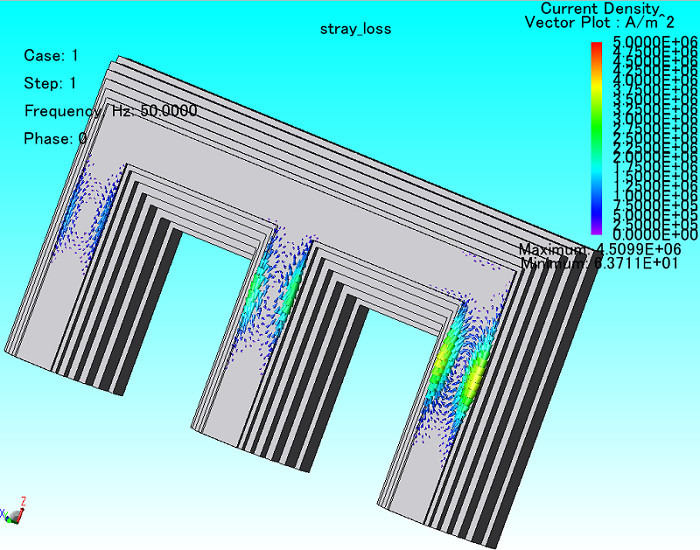
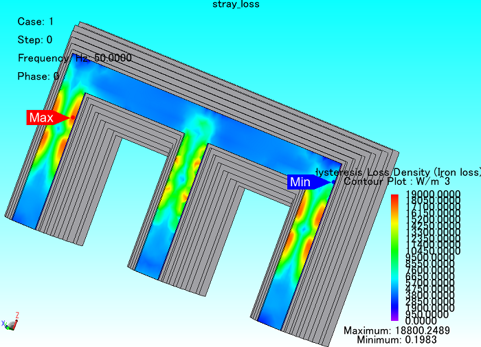
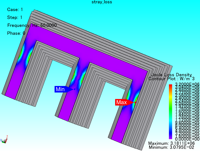
Eddy current loss density and eddy currents distribution are shown in Fig. 3 shows temperature distribution in the gear. Temperature variation versus time in one point of gear is shown in Fig. 6. Using JMAG helps to analyze magneto thermal Multiphysics of electrical devices such as induction heating.
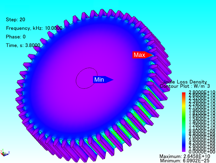 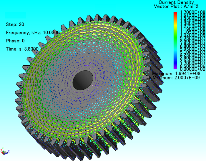 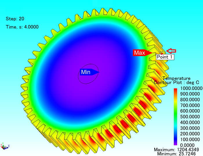 |
Fig. 3 Eddy current loss density in the gear - Eddy currents distribution in the gear - Temperature distribution in the gear
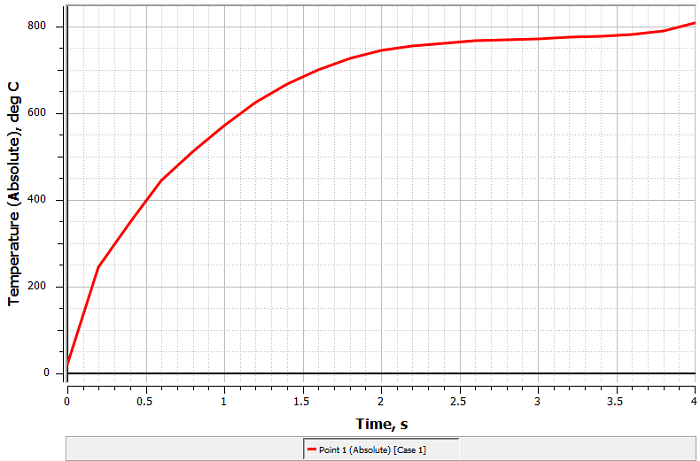
Fig. 6 Temperature versus time for one point in the gear (Point 1 in Fig. 5)